
Written by Dean Clark, European Director of Operations at ECS Inc. International
1. STM32 Processor Families
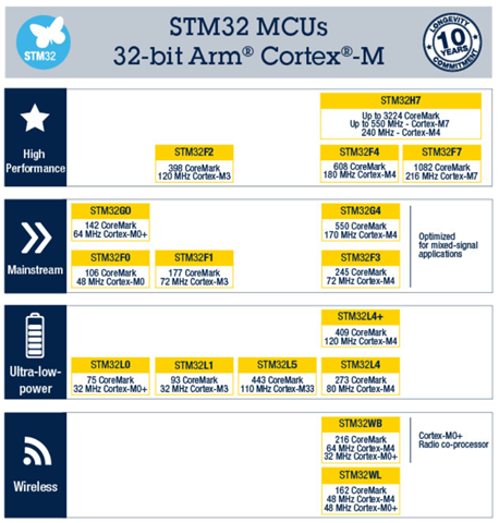
Table 1 shows the range of STM32 processor families and how they have been matched to different application verticals. Picking the desired MCU family is obviously the first choice a designer must consider. Some of these choices are outside the remit of this paper, like clocking speed, internal architecture and memory levels that impact the overall design. Power level of the architecture is the key factor for the oscillator design that follows. The designer’s choice at this stage to use an ultra-low power processor will have a major impact later in the design of the oscillator loop. Many of the STM32 MCU’s offer a variable drive level. These offer designers LSE oscillators with modifiable on the fly transconductance (dynamically) like the STM32L0 and others in this category. Other MCU’s like STM32L1, or F4, are fixed drive levels, and may have less flexibility.
Table 1 – displays the range of STM32 processor families
2. What overall considerations should a designer look at when choosing a crystal?
a. Will the crystal meet design guidelines and operate as planned?
b. Will the crystal oscillator meet the power drain needs of the application?
c. Will the crystal size fit the applications needs; is it small enough, lower drive or AEC-Q200?
d. Will the crystal meet the cost targets set by the design?
3. Spec parameters that impact STM32 MCU crystal oscillator design
a. Start-up – Start-up performance can be looked at in two ways; firstly, if the oscillator will start-up consistently in the application under environmental conditions, and secondly how long it takes to start-up at power up. The datasheet parameters that affect start-up are: CL, ESR and C0. Making any of these lower improves gain margin that improves start-up. A greater depth explanation is discussed in Section 5 that covers gain margin.
Figure 1 – Typical Vdd Rise
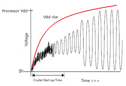
Figure 1 shows a typical Vdd rise from 0V and how oscillator closed loop gain increases until unity gain is reached, and the oscillator loop stabilizes, locking onto the resonator frequency. The time from 0V to start-up of stable oscillation is shown as start-up time.
b. Cost – Mass production volumes impacts the global market for all BOM items that make up a crystal resonator. The 3.2 x 1.5 mm size is currently the largest volume seller, so we see prices very competitive in this size. ECS has the largest selection in this size as STM32 Reference Designs, with 20 options (Ref #2 page 36). The trend towards smaller sizes are generally with 2.0 x 1.2 mm the next used option. Cost increases with further package size reduction.
c. Package Size – As mentioned above the trend is for smaller package sizes, as driven by mobile wireless solutions. ECS Inc offers the widest selection of watch crystals in the industry with referenced part numbers for all STM32 MCU’s. These range from 1.2 x 1.0 mm to 8.0 x 3.8 mm. Different package sizes offer different constraints, one of the major parameters is the ESR. Due to the crystal blank size, the ESR increases as package size reduces, this in turn impacts the gm_crit of the crystal. The ESC Selection Tool helps here, allowing the designer to make these considerations.
d. Tolerance – Most designs will look for a standard 20ppm tolerance crystal; tolerance is the manufacturing measured ppm range at 25°C. In some applications, tighter tolerance is important, and this is again where the ECS Selection Tool helps to narrow the range of options.
e. Drive Level – Drive level is an important parameter to meet at both ends of the spectrum. Too low and the crystal won’t start-up, too high and the crystal could be damaged or the oscillator loop saturate, so that loop gain drops <1 and the oscillator could stop.
- Low Drive – The ECS Selection Tool lists all parts that have a Gain Margin of 5 or greater for the specific STM32 processor with the selected or standard drive level. This ensures the crystal will start-up and is the priority. The ECS Selection Tool helps the designer to meet this mandatory requirement, but then allows you to explore options. Picking a lower gm_crit actual will mean a lower drive current through the crystal, so using less power.
- High Drive – The other extreme is more drive than the crystal and the oscillator loop can withstand. Some of the STM32 MCU’s have a HIGH DRIVE configurable setting, for these its recommended to use 12.5pF CL crystal.
Figure 2 – Consideration for Drive level STM32 MCU’s (Ref #2 page 20)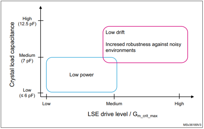
Figure 2 above taken from the STM32 AN2867 (Ref #2 page 20), shows some of the compromises to consider when using different drive levels. Often low power is the driving factor for handheld or wireless connected applications. The graph shows selecting 6pF or less CL with medium to low drive levels is a starting point for these applications. The ECS Selection Tool helps refine this; by selecting for example F0 Medium Low, the range of CL from 6pF to 4pF can be selected. Then further refinement can be made selecting size and ESR to find the best solution.
Remembering lower CL values result in increased pullability. Therefore, design variance like capacitor tolerance could lead to less accuracy or more variability in production. These lower CL crystals are also more vulnerable to noisy environments. ECS offers some of the lowest ESR’s in the industry if this is suitable workaround.
If low power is not a driving factor, a higher CL value will give more robustness to noisy environments. In these cases where MCU high drive is implemented a 12.5pF CL is advised. This will make the oscillator closed loop less vulnerable to saturation. This saturation situation occurs as the sine wave approaches the supply rails, the amplifier in the closed loop flattens (clips) the sine peaks, suddenly small signal gain instantaneously drops to zero. This only recovers when the output amplitude increases until the nonlinearity reduces the average small signal gain to one, so oscillation can continue. Remember, Barkhausen Criterion, where first condition is that the magnitude of the loop gain (Aβ) must be unity.
Overdriving is an issue for the stability of the oscillations and is manifested in no oscillation or high jitter. Equally we need to consider drive through the crystal. The spec will detail the max drive level, and testing should be done to see these criteria are not exceeded.
f. AEC-Q200 options – Automotive grade (AEC-Q200) is another often mandatory option that is required when the designer is making the crystal selection. ECS has a wide range of spec options available in package size 2.0 x 1.2 mm (12Q series) and 3.2 x 15 mm (34Q series). Some of these again can be found using the ECS Selection Tool, but a wider selection is also available in Distribution. If any help is needed to understand the gm_crit of these parts ECS will be pleased to help.
4. Oscillator loop terminology explained
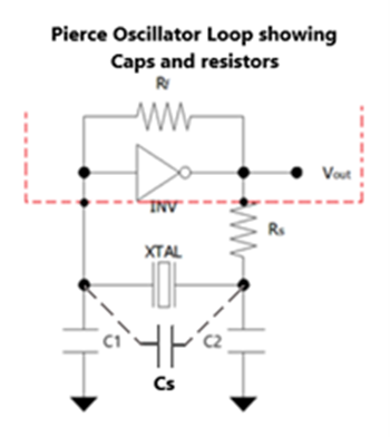
Figure 3 – Typical Pierce Oscillator Loop
Figure 3 shows a typical Pierce Oscillator loop and is common to STM32 MCU LSE crystal oscillators.
a. Inv: the internal inverter that works as an amplifier inside the processor
b. XTAL: crystal quartz or a ceramic resonator
c. Rf: internal feedback resistor
d. Rs: external resistor to limit the inverter output current
e. C1 and C2: are the two external load capacitances
f. Cs: stray capacitance, is the sum of the microcontroller pin capacitance (OSC_IN and OSC_OUT) and the PCB (a parasitic) capacitance.
. g. gm: Transconductance, where for a small signal is gm = iout / gm_crit
h. Gain Margin or (Safety Factor): gain margin = gm / gmcrit
i. gm_crit max = 4 x ESR x (2πF)2 x (C0 + CL)2, uses max parameters from crystal data sheet.
j. gm_crit actual = gm_actual = 4 x ESR x (2πF)2 x (C0 + CL)2, uses actual parameters crystal measurement.
5. Calculating Gain Margin
The calculation for Gain Margin: Gain Margin = gm / gmcrit
This is where gm is the transconductance of the inverter stage in the MCU at the dedicated drive level and gm_crit = (4 x ESR x (2πF)² x (C0 + CL)².
These are outlined in the STM32 AN2867 (Ref #2 page 22). The ECS Inc. Selection Tool has embedded these calculations to allow the user a convenient way to select the kHz crystal options to meet the needs of the LSE oscillator. All the crystals meet the gm_crit_max to attain the minimum GM (Gain Margin) of 5, however potential selections will offer even higher GM allowing the user to select different sizes, CL, ESR, Tolerance or Rating to meet application demands.
6. Calculating the External Capacitors for LSE oscillator
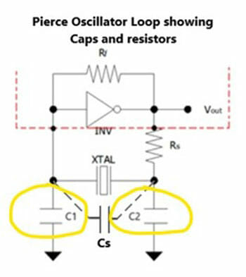
Figure 4 – Pierce Oscillator Loop Showing Caps
Figure 4 shows the external capacitors that are an integral part of the design of the oscillator loop.
The external capacitors are integral part in the design of the oscillator loop. The total capacitance C1 // C2, Cs and C-in and C-out of the MCU all combine to a Total Capacitance. This needs to be the same as the Crystal CL for the frequency to be as near as possible to 32.768 kHz.
The following formula describes how to calculate CL:
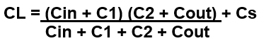
The formula includes the C-in and C-out of the MCU. The C-in is listed in the MCU datasheet, and C-out is normally approximately 2x the C-in.
The lower the crystal CL, the more impact the Cs (Board Strays) has on the capacitor calculation. As mentioned in Section 4e iii, the low CL can be used in low drive applications, but lower CL has more pullability. When using this formula, it shows how the variability of the external capacitors or board stray capacitance will pull the frequency. When considering external capacitors use COG NPO 1% types to minimize the impact of capacitance change over temperature.
7. Calculating the drive level
The drive level is an important consideration; overdriving can lead to longer term damage to the crystal, so the drive should be within the crystal drive rating found in the manufacturer’s specification.
The other less known impact comes from overdriving the sine wave, so that the sine peaks hit the supply rail. As this happens, the small signal loop gain can instantaneously drop to zero. The overall effect is the oscillator amplitude will stabilize when average gain over a cycle is one. The result of this gain averaging is harmonic distortion as seen in jitter of the output waveform.
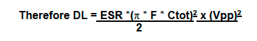
- If calculating the drive level, I recommend the method taken from the STM32 drive level recommendation (Ref #2 page 15).
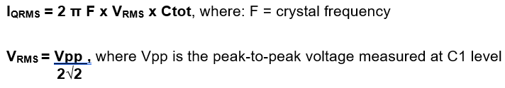
DL= I²QRMS × ESR, where IQRMS is the RMS AC current. This current can be calculated by measuring the voltage swing at the amplifier input with a low-capacitance oscilloscope probe (no more than 1 pF).
The amplifier input current is negligible with respect to the current through C1, so we can assume that the current through the crystal is equal to the current flowing through C1.
This will be in the uA range, so appropriate measurement equipment should be used.
Therefore, the RMS voltage at this point is related to the RMS current by:
Ctot = C1 + (Cs / 2) + Cprobe where:
-C1 is the external load capacitance at the amplifier input
-Cs is the stray capacitance
-Cprobe is the probe capacitance
8. Calculating External Rs value
If the drive level exceeds the crystal manufacturer’s recommendations, then two options are available to designers using the ECS Selection Tool;
- Look at crystal options with a lower actual gm_crit, this will improve the Gain Margin and lower drive current.
- Consider adding a Rs resistor. The role of the Rs resistor is to limit the drive current in the crystal.
- An initial estimation of Rs can be obtained by considering the voltage divider formed by Rs and C2. Thus, the value of Rs is equal to the reactance of C2. Therefore Rs = 1 / (2 π F C2),
- After picking the estimated Rs, then the gain margin needs to be recalculated but with Rs added to ESR
Gm_crit with Rs = 4 × (ESR + Rs) × (2 π F)² × (C0 + CL)²
Gain Margin = gm / gmcrit with Rs
ECS Inc. has created a STM32 crystal selection tool that makes choosing the correct kHz or MHz crystal easier. This tool has been specifically designed for the range of STM32 MCUs and is updated daily. For questions about frequency control and STM32 MCUs, contact the engineering support team at engineering@ecsxtal.com.
References:
Ref #1 – https://www.st.com/en/microcontrollers-microprocessors/stm32-32-bit-arm-cortex-mcus.html
For more technical resources, please reference our library of technical guides, educational video library on frequency control and product information, our reference design library or our current product catalog.
Please contact us if you need additional information or have a specific requirement in your application.
ECS Inc. International
15351 West 109th Street
Lenexa, KS 66219
Tel: 913-782-7787
Toll Free: 1-800-237-1041
Fax: 913-782-6991