
Written by David Meaney, Vice President of Global Technical Sales and Marketing at ECS Inc. International
Many of today’s technologies require crystal devices to produce a stable clock reference signal for optimum performance. In these systems, a need to compensate the crystals to minimize the effects that temperature variations have on the crystals frequency. When combined with an appropriate chipset, a thermistor crystals precision temperature compensation can offer very tight frequency stabilities. This makes them ideal for precision applications and as a viable replacement for TCXOs.
By combining the crystal and thermistor integrally in the same hermetically sealed package, you get several advantages over traditional separate crystal and temp sensor. First, thermistor proximity gives real time crystal temperature feedback. It also minimizes part count, saving board space and simplifying circuit design. These crystals with integral thermistors offer significantly better stability over temperature performance than standard non-compensated crystals. In short, thermistor crystals can be used to improve temperature stability by more than 20x over a standard crystal or oscillator.
What is a Thermistor Temperature Sensor?
The thermistor is a resistor whose resistance varies with changes in temperature. Thermistors are found in many everyday products and are used as basic temperature sensors. Thermistors are made up of metallic oxides, binders, and stabilizers. The ratio of the composite materials decides their resistance/temperature curve. In the manufacturing process this ratio needs to be monitored closely, since it determines the thermistor accuracy.
There are Two Types of Thermistors
- NTC Thermistors: “Negative Temperature Coefficient”, where the resistance decreases as temperature rises. The NTC is commonly used as a temperature sensor, or in series with a circuit as an inrush current limiter.
- PTC Thermistors: “Positive Temperature Coefficient”, where the resistance increases as temperature rises. PTC thermistors are commonly installed in series with a circuit, and used to protect against overcurrent conditions, as resettable fuses.
How do Thermistor Crystals Work?
In very basic terms a thermistor crystal operates by employing a temperature compensation network that senses the ambient temperature at or near the crystal and continuously applies frequency correction to pull the crystal back to its nominal value. The idea is that the compensation network drives the pulling network, which then adjusts the output frequency of the oscillator.
In a normal oscillator circuit, the nominal frequency tolerance of the quartz crystal will range from 5 ~ 10ppm when monitored at room temperature (+25°C). Depending on the cut of the crystal you will see significant frequency drift over the specified operating temperature range. This is the “temperature stability”. Thermistor crystals allow you to interpret the temperature feedback and apply the appropriate compensation to keep the crystal on frequency and as stable as possible.
Thermistor Feedback
The thermistor offers a varying resistance based on measured temperature. For the appropriate compensation to be applied to the crystal we need to understand the resistance and derive a precise temperature measurement. Then we can convert that resistive feedback to a voltage that will be applied to the crystal as a frequency correction. This is done using the Steinhart-Hart Equation.
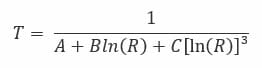
Where:
T is the temperature (in kelvins),
R is the resistance at T (in ohms),
A, B, and C are the Steinhart–Hart coefficients, which vary depending on the type and model of thermistor and the temperature range of interest.
Crystal Stability
Crystal stability is defined in two ways: tolerance is the measure of frequency drift at room temperature, stability is the frequency drift over the rated temperature range. The nominal frequency is measured at +25°C. Then the frequency drift over temperature is reference as a ± ppm above and below the nominal frequency. This is measured across the rated temperature range. (Example ±50ppm, -40°C ~ 85°C referenced to +25°C) is telling us that the nominal frequency will not deviate more than 50ppm above or below the nominal frequency across the rated temperature range.
Compensation
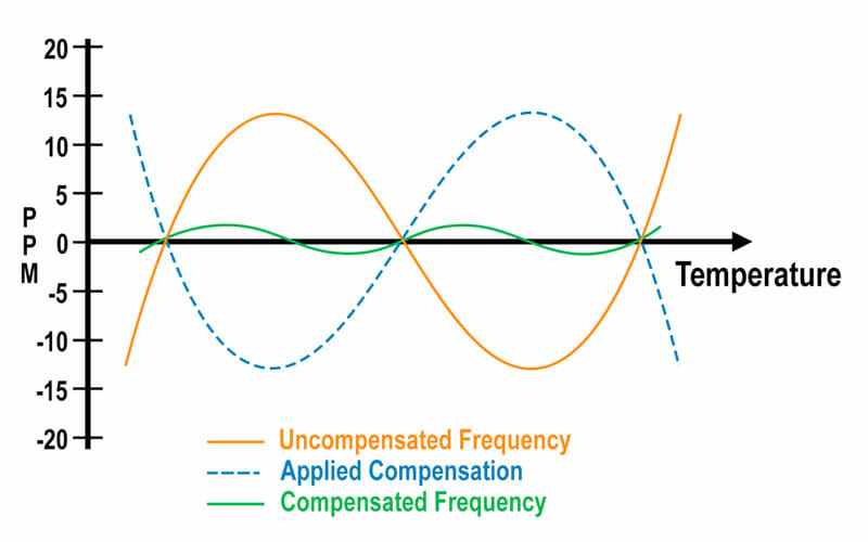
The figure below represents the function of the thermistor crystal oscillator circuit. The uncompensated oscillator’s frequency response to temperature in orange and the compensating voltage as derived from the thermistor feedback in blue. It is like a 3rd or 5th order polynomial curve depending on non-linearities. The goal of the compensation network is to produce a voltage that mirrors the effects of frequency drift caused by changes in temperature. When the correction voltage is applied, we can effectively cancel out the frequency drift caused by temperature. This resulting much more stable frequency/temperature curve is plotted in green.
Thermistor Crystal with an Arduino
OpenQCM has a paper on how to achieve highly accurate quartz crystal microbalance accuracy-based temperature measurements, using an Arduino thermistor.
For more information on using thermistor crystals with an Arduino please visit OpenQCM
To view ECS Inc.’s thermistor offering, click here.
For more technical resources, please reference our library of technical guides, educational video library on frequency control and product information, our reference design library or our current product catalog.