
Written by David Meaney, Vice President of Global Technical Sales and Marketing
The most common questions asked about oscillators is: what is the difference between single-ended and differential outputs, and what applications are they best suited for?
Depending on the application and required frequency of operation, there are several output types available to choose from. Here are a few of the different outputs in more detail to better understand the benefits and tradeoffs of each. This should give you a better idea of which type is best for your application.
There are two main output formats that are used.
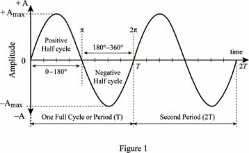
Sine wave – as shown in the graph below creates a continuous analog sinusoidal wave that is denoted by sweeping cycles at the rate of the frequency and amplitude.
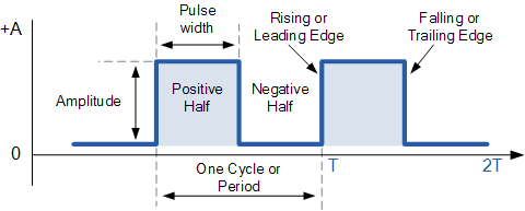
Square wave – as shown in the graph below is a digital representation of the oscillator output. Its signal is denoted by 90-degree cycles at the rate of the frequency and amplitude.
The outputs we will cover are:
Single Ended Output:
- Sine Wave and Clipped Sine Wave
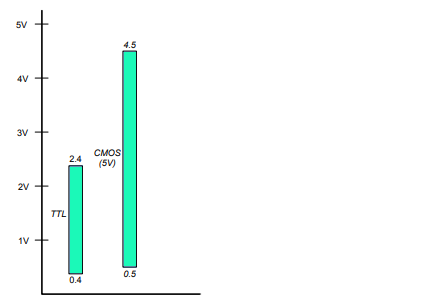
- TTL (Transistor to Transistor Logic) 0.4 ~ 2.4V
- CMOS (Complementary Metal Oxide Semiconductor) 0.5 ~ 4.5V
- HCMOS (High Speed CMOS) 0.5 ~ 4.5V
- LVCMOS (Low Voltage CMOS) 0.5 ~ 4.5V
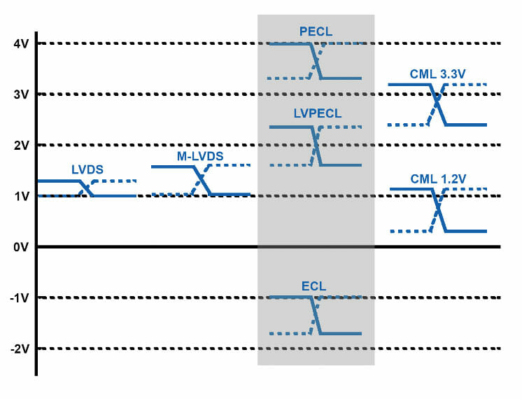
Differential Output:
- PECL (Positive Emitter Coupled Logic) 3.3 ~ 4.0V
- LVPECL (Low Voltage PECL) 1.7 ~ 2.4V
- CML (Current-Mode Logic) 0.4 ~ 1.2V and 2.6 ~ 3.3V
- LVDS (Low Voltage Differential Signaling) 1.0 ~ 1.4V
- HCSL (High Speed Current Steering Logic) 0.0 ~ 0.75V
Which Oscillator Output Signal Type is Best Suited for Your Application?
Let’s look at the strengths and weaknesses of each.
We’ll start with basic and look at the single ended options first:
Sine Wave and Clipped Sine Wave
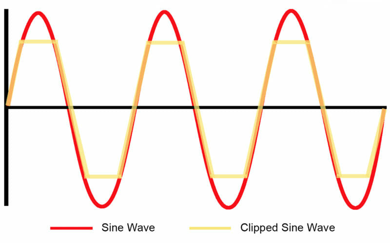
Sine Wave — is the standard or ‘natural’ signal output of a crystal or oscillator circuit. It consists of one fundamental sinusoidal frequency output. The linearity sine wave outputs offer the best phase noise performance of all the outputs. These are great for applications that require a high-quality output signal.
Clipped Sine Wave — the sine wave output is manipulated so it will not reach its max high or low. By doing this you are creating a square wave output without sacrificing any of the desired phase noise performance.
In this illustration you see a sinusoidal wave in red and the clipped sine wave in yellow.
CMOS, HCMOS and LVCMOS
CMOS, HCMOS, and LVCMOS all fall under the Complementary Metal Oxide Semiconductor category. They are a square wave digital output most suitable for lower frequency clocking, typically below 250 MHz. This allows for a direct connection between the clock output and chip input. In most cases, a low value series resistor can be used to effectively reduce signal feedback and maintain a reliable signal integrity. There are also high speed and low voltage options that may fit better with your specific needs.
TTL or Transistor to Transistor Logic
This is an older digital output standard and has mostly been replaced by CMOS technology. This is because CMOS provides lower costs and better noise performance. Both CMOS and TTL are great for low power consumption, higher output swing, with a relatively low cost.
Differential Output Signal Options
A differential output offers dual output signal lines that are 180° out of phase. This has many benefits to the signal quality, including:
- Better rise and fall time
- Superior jitter and phase noise performance
- Improved common-mode noise rejection
- Helps reduce electromagnetic and radio frequency interference
ECL or Emitter Coupled Logic
ECL was mainly introduced as a good alternative to TTL. ECL circuits can change state very rapidly which makes it better suited for high-speed data transmission. One of the disadvantages of differential outputs is they require significantly higher supply current to operate. ECL also uses a negative power supply during use. This can create challenges when trying to connect to positive base power supply devices.
PECL and LVPECL
PECL outputs are frequently used in high-speed clock distribution circuits. This is because PECL provides high noise immunity, the ability to drive high data rates over long line lengths, and good jitter performance due to the large voltage swings. However, PECL requires high power consumption to operate, which is the main disadvantage.
LVPECL provides a good foundation for Gigabit Ethernet and Fibre Channel usage. LVPECL is like LVDS electrically but provides a larger differential voltage swing and slightly less power efficiency. Challenges may arise with the output from LVPECL because termination is needed to emit a voltage. Also, the differential circuits in chips may have different input tolerances. Be sure to check for proper termination for best performance.
Current-Mode Logic (CML)
CML has similar performance to that of a LVPECL. The main difference here is that CML does not require an external bias. This makes CML a good alternative to LVPECL when low power is a concern.
Low Voltage Differential Signaling (LVDS)
LVDS is like LVPECL output, however the power consumption for LVDS is lower and tends to have smaller voltage swings. LVDS is typically used for high speed data transfer needs like clock distribution or backplane transceivers. For higher data rates, HCSL, CML or LVPECL are usually preferred, but will require more power consumption than LVDS. Other benefits include reduced susceptibility to noise and are easy to implement in CMOS ICs.
A disadvantage to LVDS is its reduced jitter performance compared to PECL, but new technology is being looked at to achieve the same level of jitter performance as LVPECL.
High Speed Current Steering Logic (HCSL)
HCSL has a newer output standard that is like LVPECL. One advantage of HCSL is its high impedance output with quick switching times. A 10 to 30-ohm series resistor is recommended to reduce possible overshoot and ringing. Other advantages include the quickest switching speeds, low power consumption (between that of LVDS and LVPECL), and average to good phase noise performance.
A quick recap:
For ease of use: An LVDS output requires only a single resistor at the receiver, whereas LVPECL requires termination at both transmitter and receiver.
For higher frequencies: LVDS, LVPECL and HCSL have faster transitions than CMOS but will require more power.
For lowest power consumption: we recommend using CMOS or LVDS if your frequency is above 150 MHz.
For best jitter performance: LVPECL, LVDS, and then CMOS if your frequency is low enough.
For more technical resources, please reference our library of technical guides, educational video library on frequency control and product information, our reference design library or our current product catalog.
Please contact us if you need additional information or have a specific requirement in your application.
ECS Inc. International
15351 West 109th Street
Lenexa, KS 66219
Tel: 913-782-7787
Toll Free: 1-800-237-1041
Fax: 913-782-6991