
Written by David Meaney, Vice President of Global Technical Sales and Marketing at ECS Inc. International
What is a Power Inductor?
A power inductor, also called an inductor coil and choke inductor, is a passive electronic component consisting of wire round around a core of ferrite that includes an air gap that is used to clean up the output from high frequency switch power supplies.
Selecting an inductor is more complicated than just choosing the inductance value. To be confident that the inductor will perform in your circuit, there are other specifications that will need to be considered. Power inductors can be categorized by the following factors:
- DC resistances
- Tolerance
- Package size
- Nominal inductance
- Packaging
- Shielding
- Maximum rated current
Inductor Construction and Operation
An inductor is characterized by its’ form and materials. They are formed by using insulated copper wires that are wound in a coil around a core material, commonly ferrite, making it a two terminal passive inductor. When the current flows through the wire, an electromagnetic field will develop, and the EMF will generate depending on the rate of change of the magnetic flux. Inductors typically offer low magnetic radiation for low noise environments by storing energy in its’ magnetic field.
In a circuit, power inductors operate as energy-storing devices. They store it in a magnetic field when current flows through them during the circuits on time and can deliver that energy to the load during its’ off time.
AC vs DC Currents
To understand the behaviors of the AC and DC to a power inductor, Lenz Law needs to be understood. Lenz Law describes the reaction when the direction of the current induced in a conductor by a changing magnetic field creates a magnetic field that opposes the change that produced it.
When AC flows through an inductor, it disrupts the flow and is opposed by the inductor by increasing the reactance. According to Lenz Law, this creates a magnetic field in which the intensity is determined by the frequency of the AC. The higher the frequency of the AC, the higher the rate of change current and blocking effect from the inductor.
A steady DC flowing through an inductor produces a uniform magnetic field and the magnetic flux remains constant. The steady DC produces zero current change. From this, there is no self-induction or self-induced EMF therefore there was no voltage induced and the inductor does not oppose the DC.
Inductance and Tolerance
Inductance is defined as the electromotive force of any electric circuit that is created as the result of a changing current. Any power inductor can oppose a change in current flow to intentionally prevent signals with a higher frequency from passing, or choking off higher frequencies, while allowing signals of lower frequency to continue. This property is why inductors are commonly referred to as “chokes”.
This reactance will create resistance to alternating currents (AC) while allowing the direct current (DC) to flow through it, but often an inductor will encounter ripple voltage. Ripple voltage is a term used to quantify the amount of AC voltage that still appears on DC voltage when the converter converts the AC into DC.
A power inductor that will be used for smoothing out the ripple current from the output of a DC/DC power supply may be specified with a ±20% inductance tolerance. Tolerance is the difference in the inductance value of an actual inductor compared to the specified value in the data sheet. Typically, tolerance is specified at room temperature while understanding that the actual inductance will vary significantly across a wide temperature range.
Understanding the inductance change over the expected operating temperature range is critical because depending on the application, specified tolerances will vary. Typical wire wound and ceramic inductors have a temperature coefficient of inductance range of +25 to +125 ppm/°C. Inductors with ferrite cores will have much wider temperature coefficients of inductance of 700 ppm/°C or higher.
Does Inductance Vary with Frequency?
Yes, inductance of an inductor will increase when the frequency of the applied voltage increases.
In a typical inductor, the nominal inductance increases to a peak, incurs parasitic capacitance, and becomes zero at the self-resonant frequency of the inductor. Up to the resonance frequency point, the inductance trait common in the inductor is displayed, but beyond the resonance frequency, the parasitic element becomes dominant.
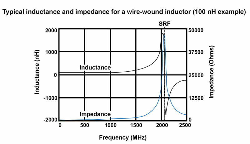
Figure 1 illustrates the apparent inductance as measured by a LCR meter. An LCR meter is a type of electronic test equipment to measure the inductance (L), capacitance (C), and resistance (R) of an electronic component.
To avoid interference in the frequency band, inductors are selected to avoid operation in the frequency region near the self-resonant frequency. When selecting an inductor, it is crucial to know what frequency was used to arrive at the data sheet specification.
Ampere and Faraday’s Laws
Inductors operate based on two laws of electromagnetism – Ampere’s Law and Faraday’s Law.
Ampere’s Law
Ampere’s Law describes the relationship between the current in the wire wound around the core to the magnetic field inside the core of an inductor. It states that for any closed loop path, the sum of the length multiplied by the magnetic field in the direction of the length is equal to the permeability multiplied by the electric current of the loop.
Understanding the givens via the data sheet of specified inductor, the strength of the magnetic field can be determined by:

Where
B is the magnetic field
µ is the current
I is the inductance
n is the number of coils
Faraday’s Law
Faraday’s Law relates the process of how any change in the magnetic environment of a coil of wire will cause a voltage (emf) to be induced in the coil. The induced emf in a coil is equal to the negative of the rate of the magnetic flux change multiplied by the number of turned in the coil. The voltage could be generated by any change such as changing the magnetic field strength, moving a magnet to or away from the coil, moving the coil into or out of the magnetic field, or rotating the coil relative to the magnet. The emf units are volts.
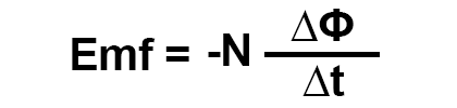
Where
N is the number of turns in the coil
Φ is the BA, or the magnetic flux
B is the external magnetic field
A is the area of the coil
t is the time
These two laws deduce that because ferrite materials, the typical material for an inductor core, have high permeability, they create an environment for low reluctance, or easy magnetic flux This helps contain the flux to the inductor’s core which enables inductors with high values and small size.
Where are Inductors Used in Everyday Life?
A major detriment to proper function of modern electronics is the power source used. An unstable voltage, phase noise, and varying current are just some factors that can cause improper function or even failure. A ‘dirty’ power source can be mitigated. Inductors are a way to remove voltage, spurious noise, and current fluctuations from power supplies. The primary function of a power inductor is to ensure a clean, stable DC power supply.
Applications for low DC resistance shielded inductors:
- DC/DC line conditioning
- AC/DC power supplies
- Digital switch mode power supplies
- Differential mode filtering
- Signal line chokes
Additional inductor applications:
- RF tuning circuits
- RFI elimination
- Energy storage
- Signal line chokes
- Inductive sensors
- Filters
For more technical resources, please reference our library of technical guides, educational video library on frequency control and product information, our reference design library or our current product catalog.
Please contact us if you need additional information or have a specific requirement in your application.
ECS Inc. International
15351 West 109th Street
Lenexa, KS 66219
Tel: 913-782-7787
Toll Free: 1-800-237-1041
Fax: 913-782-6991