
Written by David Meaney, Vice President of Global Technical Sales and Marketing at ECS Inc. International
Introduction to Inductors
As modern electronics have continued to become more and more sophisticated, today’s microcontrollers (MCUs), digital signal controllers (DSCs) and microprocessors (MPUs) are performance dependent on a steady, clean supply of DC power. This has put a lot of pressure on modern power supplies to be more efficient and provide much cleaner power for processing, data storage and networking.
A universal increase in the need for processing and connectivity is steadily increasing the need for clean and steady power for sensitive electronics. This makes choosing the correct inductor a critical part of the overall design. Engineers need to understand the power requirements of their system in order to design in an appropriately specified inductor. This paper will guide in determining an inductor’s power handling and losses by reviewing the critical specs of an inductor to ensure it meets the performance characteristics of your design. The power strength of an inductor can be estimated using the data sheet specifications for current and resistance.
Topics covered:
- Maximum operating temperature
- ESR – Equivalent series resistance
- DCR – Direct current resistance
- Irms and Isat
- Power dissipated
- Current ratings
- Power losses
Maximum Operating Temperature
The maximum operating temperature of an inductor is defined by measuring the combined maximum temperature of the inductor under all conditions including ambient temperature and self-heating due to current.
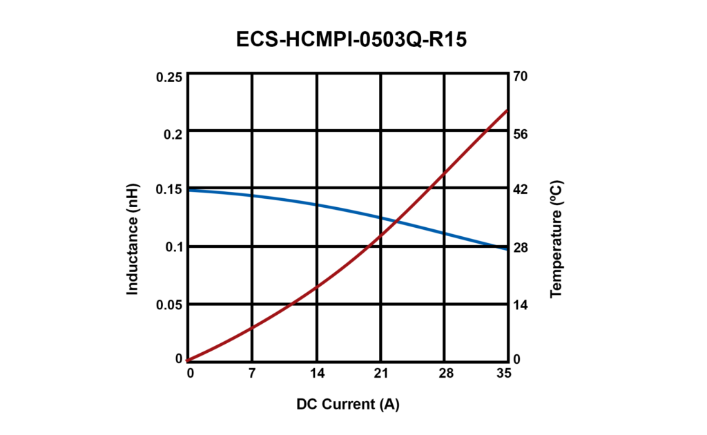
Using part number ECS-HCMPI-0503Q-R15 as an example, it lists a 0.15 µH with a 22.2A current rating and a 36A typical saturation current. The saturation current is the point where the magnetic field no longer increases proportionally with an increase in current. The core has become ‘saturated’.
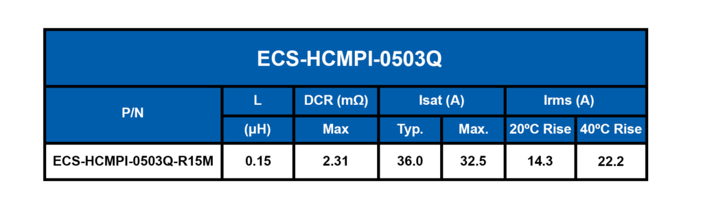
At ECS-HCMPI-0503Q’s rated 22.2 A current we can see the L inductance will be 0.07 µH at 34°C. As the current increases we can see from the graph below, the L inductance decreases. Note in their specs at saturation current the inductance has decreased by 30% of the nominal rating of .15 µH.
Test conditions:
Test frequency: 100 kHz / 0.1V
Isat: Based on inductance decrease 30%
Irms: Based on temperature decrease 40ºC
Operating temperature range: -40ºC ~ +125ºC
What is ESR?
Inductors have resistance from the wire used to make the coil. This resistance is called the equivalent series resistance, or ESR. The ESR is often used to calculate resistive losses in inductors. It plays an important role in designing a power efficient inductive choke. The ESR of an inductor is made up of two elements: DC resistance and frequency-dependent resistance. The DC resistance can be calculated using Ohm’s law. An inductor’s ESR is particularly important in applications with low duty-cycle, high-frequency current pulses.
What is DCR?
Inductors allow DC (direct current) signals to pass through while blocking all high-frequency AC (alternating current) signals. Inductor DCR (DC resistance) is the amount of resistance an inductor presents for signals with frequencies of or near 0 Hz. The DCR is the resistance component of the coil of wire. It is important to consider the acceptable DCR of the inductor according to your application. Inductors with high DCR will have high losses which is bad for circuit efficiency. So, it is always better to select an inductor with lower DCR value when possible.
- In a DC circuit, an inductor appears as a short circuit with very little resistance.
- In an AC circuit, an inductor acts like a resistor thats value depends on the frequency of the AC source.
Current Ratings for Inductors
The current rating for the inductor, either chip inductor or power inductor, may specify either a saturation current (Isat), rms current (Irms), or DC current (IDC) current.
The Irms rating is a measurement derived from heat rise and reliability due to average inductor current while the Isat rating is a performance indicator related to the instantaneous inductor current.
The Isat is lower than Irms for some inductors. This means that before the component temperature reaches its performance limit, the core will saturate. In this instance, the Isat may be specified as the limiting factor. The more common occurance is where the Isat is higher than Irms, the Irms would be specified and the temperature rise above ambient.
For a standard ECS Inc. International inductor, we determine Irms current rating.
The root means square (Irms) current rating is an indirect measure of inductor temperature rise to be expected from a given amount of power dissipation over 25°C ambient. This rating represents two factors: how much power dissipation is caused by an inductor current and how much temperature rise is a result of that power dissipation.
The Irms rating is not intended to capture all possible forms of power loss due to application conditions, only temperature. Because of this, the limitation is generally the temperature rating of the insulating materials in the inductor. Therefore, the Irms rating is a measure of how much current may be allowed in the inductor to ensure safe and reliable operation without heat damage to the inductor. Calculating the Irms current rating can be done by determining the circuit’s maximum current.
= I2R
Where:
R is the DCR of the wire winding
I is the average or DC value of the inductor current
Calculate the Power Dissipated by Inductors
To calculate the DC power dissipated by the inductor, use:
Pdc = Irms2 x DCR
To calculate the AC power dissipated by the inductor, use:
Pac = Irms2 x ESR
Where:
Pdc is the DC current through the inductor
Pac is the AC current through the inductor
DCR is the DC resistance of the inductor
Irms is the current through the inductor
ESR is the equivalent series resistance of the inductor
To calculate the total power dissipated by the inductor, use:
Ptotal = Pdc + Pac
Ptotal = (Idc2 x DCR) + (Irms2 x ESR)
Calculating Inductor Power Losses
Temperature, frequency, and the AC and DC currents can all impact inductor power loss. Calculating inductor power loss for a specific application may be complicated, but there are equations that can provide estimations.
To calculate inductor power loss, use:
PlossInductor = Pcore + Pdcr + Pacr
Calculate Pcore
Measuring core loss and getting accurate, repeatable results can be tedious for a design engineer. Typically, the calculated core loss can be acquired from the inductor provider, otherwise a formula can be used to calculate core loss.
Pcore (mW) = K1FxBy x Ve
Where:
K1 is the constant for core material
F is the frequency (kHz)
B is the peak flux density (kGauss)
x is the frequency exponent
y is the flux density exponent
Ve is the effective core volume (cm3)
Calculate Pdcr
An inductor’s DCR is the opposition to current flow through the inductor coil (P=Core). Because of this opposition to current you will have current losses in the coil. This is the measure of Pdcr. The wire loss caused by Pdcr is the easiest component to calculate.
Pdcr (W) = Irms2 x DCR
Where:
Irms is the rms value of the peak current
DCR is the DC resistance of the inductor
Calculate Pacr
The wire loss caused by AC resistance can be difficult to calculate because values like the AC winding resistance may not be readily available from vendors.
Pacr (W) = Irms2 x ACR
Where:
Irms is the rms value of the peak-peak ripple current
ACR is the AC resistance of the inductor
For additional information on power inductors, please visit our Introduction to Power Inductors technical guide or watch our power inductors product overview video.
To see our full line of power inductors, click here.
Please contact us if you need additional information or have a specific requirement in your application.
ECS Inc. International
15351 West 109th Street
Lenexa, KS 66219
Tel: 913-782-7787
Toll Free: 1-800-237-1041
Fax: 913-782-6991
Specifying Inductor Values was last modified: October 12th, 2023 by