
Top Considerations to Ensure Exceptional Designs
When you plan to use a crystal oscillator on your circuit board design for frequency control, certain engineering considerations give your project two key advantages: reliability and high performance. The application that uses your design can benefit from the communication, synchronization and orchestration that a frequency signal provides.
Therefore, a design that includes a frequency solution must focus on making considerations regarding the following parameters, which allow you to select products and make design decisions that will ultimately benefit your project:
- Selecting series versus parallel crystal resonators
- Load capacitance
- Frequency tolerance and stability
- Crystal aging
- Equivalent circuit design
- Field vibration
- “Q” factor
- Soldering
- Ruggedization
- Trim sensitivity
Series Versus Parallel Crystal Resonators
It is important to understand whether your crystal resonator depends on a phase shift from a reactive component. This ensures that the crystal you have picked works properly within your design.
- Select a parallel crystal resonator when there are reactive components (like capacitors) in the oscillator’s feedback loop.
- Choose a series resonator when there are not reactive components.
Consider Load Capacitance
Capacitors included in a parallel crystal resonator create external capacitance. This must be specified to ensure that this external capacitance does not affect the frequency signal. Use this tool to calculate your crystal oscillator circuit’s load capacitance.
Understanding Tolerance and Stability
At room temperature, +25˚C, a crystal can allow (or “tolerate”) a certain amount of deviation in frequency and continue to provide an effective signal. After you’ve made a determination of the temperature range your design will experience, you can calculate frequency stability, which is how much deviation to expect at a specified temperature. Engineers may consider temperature compensation from a TCXO or OCXO to ensure the best stability possible for their design.
What to Know About Crystal Aging
All crystals experience frequency change over time. However, aging can be counteracted very simply: your timing solutions product manufacturer likely designs pre-aged crystals. Further design choices can also limit aging, including ensuring a proper operating temperature, careful engineering to limit fatigue, wear and friction and reducing drive levels.
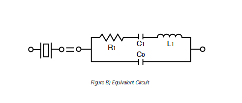
Gain an Awareness Of Equivalent Circuit Design
Refer to the visual representation below. Understanding this diagram allows engineers to mirror the basic elements of how a crystal oscillator operates. This includes the amount of opposition (impedance) of the oscillator against the alternating current (AC) flow, which helps you to determine what losses will occur in the design.

Field Vibration Basics
The physical stability of your crystal oscillator’s circuit design can limit vibration, particularly if mechanical vibration is necessary due to mechanical amplification. Although timing components can handle a normal amount of vibration, take extra precautions to limit excessive activity. Pay close attention to how you mount, encapsulate and position your crystal on your board – and keep in mind that ruggedization may affect frequency stability and crystal aging.
All About “Q” Factor
Seek out a crystal with a high “Q” factor for maximum stability and a reduced energy loss in comparison to the crystal’s stored energy. “Q” factor is determined by the bandwidth between the series and parallel frequency. The smaller the bandwidth, the higher the “Q” factor.
High “Q” factor crystals are also less sensitive to pullability, or the effect of load capacitance on frequency. If you decide on parameters that require a lower “Q” factor, pullability may lead you to including a VCXO in your design to fine-tune your desired frequency.
Soldering High-Quality Crystals and Crystal Oscillators
When soldering, protect against heat shock. Heat shock causes the solder to melt and damages the oscillating component or degrades solder contact.
For printed circuit boards (PCBs) and substrates, consider these soldering methods:
- Wave or dual wave.
- Hot air or convection flow.
- Vapor phase reflow.
- Infrared reflow.
- Bubble solder immersion.
- Additional methods, including laser soldering.
For SMD crystals, consider these soldering methods:
- Infrared reflow.
- Vapor phase reflow.
Learn Your Crystal’s Impedance and Reactance Curve
Zero phase means that your circuit’s input and output currents are at zero degrees, which is the “sweet spot” for frequency stability. A crystal’s frequency is at zero phase at two points. At series resonant frequency, energy loss is at its lowest. At anti-resonance frequency, energy loss is at its highest point. Understanding a crystal’s overall energy loss allows you to optimize your component selection and design to ensure efficient energy usage and high performance.
A Word On Shock Protection
Although oscillators can absorb normal shock events, shock pulses in the field may pose an issue for frequency performance. Ensure that oscillators are isolated from equipment with the potential to shock.
Measuring Trim Sensitivity
As load capacitance changes, frequency will change incrementally, as frequency signals are particularly sensitive. Trim sensitivity is expressed in parts per million (ppm) and parts per fraction (ppf). It is important to account how capacitors affect the overall precision and stability of your frequency signal.
Go Deeper With Additional Crystal Oscillator-Based Engineering Resources
To learn more about the aforementioned parameters and considerations, explore this article, which includes additional information, including useful figures, formulas and essential crystal equations to make excellent design decisions.
However, the principles and knowledge provided here are only as strong as the products you select. Work with a veteran team for frequency control solutions that offer a range of product options, including VCXOs, TCXOs and OCXOs, that meet your design parameters and strengthen your design. A veteran team will likely also provide engineering support, so you can depend on their knowledge for samples, prototyping, design help, testing, optimizations and more.
What separates your work from the rest is your attention to detail, time-honored practices and partnerships that provide additional value. These skills and opportunities empower you to make an impact on the industry you design for, while also providing an opportunity to practice engineering at the highest level.
Strong Engineering Principles for Crystal Oscillator-Based Designs was last modified: August 1st, 2024 by